LMS Milk Tank

Discuss freight and rolling stock here
Paul
Cleaner
Posts: 13
Joined: Wed Oct 05, 2005 12:05 am
Location: Bristol

Post by Paul » Sat Jun 20, 2009 12:40 am

Well after posting a request for pics I thought it would only be fair to post a few of my own milk tank! Click on the images to see enlarged and full size views.

These pics show the most recent activity that has taken place on the chassis, this has mainly involved dissassembly!

I have taken off all 4 brackets that retain the buffers as I had rivetted each one on upside down. I have also taken off the headstocks to square off the corners a la Keith with P38 filler. It definitely makes a difference in my opinion. I'm not entirely happy with the filler as yet as I still have a few chips on the corners that have appeared but they're not far off. Also in the pics are two of the tank bracket's which I have also used a small amount of filler to hide the punch marks used to retain the slot and tab parts during soldering. I decided that this wasn't a good idea due to the scaring it caused, hence the filler.

Paul

Image

Image

Image

Image

Image
Keith1500
Fat Controller
Posts: 150
Joined: Tue Jul 04, 2006 8:27 pm
Location: B/Hill, Essex

Post by Keith1500 » Fri Jun 26, 2009 1:44 pm

Richard Phillips
Fat Controller
Posts: 178
Joined: Mon Feb 23, 2009 6:14 pm

Post by Richard Phillips » Wed Jul 15, 2009 1:50 pm

Just starting on the leaf springs. Not sure I've got the curve right, probably a little over-done, maybe it will settle with 3000 Gals of milk on board :)

Image


The leaf spring is not slotted in this picture as yet.
Richard Phillips
Fat Controller
Posts: 178
Joined: Mon Feb 23, 2009 6:14 pm

Brake lever arrangement

Post by Richard Phillips » Tue Aug 11, 2009 9:39 am

It's like threading a needle and the clearance is pretty tight, but the prototypical bends in the lever are about all that will fit!

Image
Keith1500
Fat Controller
Posts: 150
Joined: Tue Jul 04, 2006 8:27 pm
Location: B/Hill, Essex

Post by Keith1500 » Tue Aug 11, 2009 1:32 pm

You're well on-track to have the milk tank on the rails soon I'd say. Looks like you just need a set of wheels!

Is there a drawing for the wheels do you know? or is it just a case of simply putting the profile on the blanks with out reducing the diameter any/too much and then making a set of axles to fit the boxes and give the right back to back.

Keith
Richard Phillips
Fat Controller
Posts: 178
Joined: Mon Feb 23, 2009 6:14 pm

Post by Richard Phillips » Tue Aug 11, 2009 3:52 pm

Assuming you have the same wheels I do Dave has advised taking 1mm off the back of the rim (the side with the boss projecting past the rim) and then I guess we turn to the GL5 profile. I've enquired about the "full" diameter so I'll let you know. Back to back distance on the axle shoulders should be 113 as the boss is 3mm projecting.
Keith1500
Fat Controller
Posts: 150
Joined: Tue Jul 04, 2006 8:27 pm
Location: B/Hill, Essex

Post by Keith1500 » Tue Aug 11, 2009 10:37 pm

Ah, I would never have thought of removing 1mm from the back and leaving the boss proud, or any from the face but i guess that figures as it "cleans" up and trues the wheel.

I may grab an off-cut of bar and make up a complete axle.

I wonder - should the axle be parralell between the wheels or tappered?
Dave Noble
Fat Controller
Posts: 164
Joined: Mon Feb 27, 2006 12:38 am

Post by Dave Noble » Tue Aug 11, 2009 10:58 pm

RE tyre size.

The nearest bar I could get at the time was 110mm, the tyres can be finished anywhere between 3' - 7 1/2" and 3' - 6". Sorry you'll have to remove the waste, but you should have seen the struggle we had getting thre bar from the road outside our house where it was delivered, round the back and up to the workshop. It weighed 142kg. Eventually we put a couple of turns of rope around one end, brought the citroen round, lowered it on it's suspension, tied on the rope, raised the suspension, then towed it round. Poor old band saw didn't know what had hit it.

A standard LMS 12 ton axle was 4 7/8" in the centre, 5 1/2" behind the wheel. Some coach axle drawings show them to be essentially the same size (though I would have expected them to be bigger), so I'd stick with those sizes - unless someone knows otherwise.
Keith1500
Fat Controller
Posts: 150
Joined: Tue Jul 04, 2006 8:27 pm
Location: B/Hill, Essex

Post by Keith1500 » Wed Aug 12, 2009 8:12 pm

Good grief Dave ! Hope you had you're safety foot wear on !

ok, now the tricky bit... how do you convert to scale measurements?

for a wheel size of 3'-71/2" will equal?

convert to inches and scale...
43-1/2" divide by 11.3 = 3.849inches or 3849 thou. Is that right?

convert to mm...
3.849thou divide 25.4 = 97.76mm, which seem to be in the right ball park given the stock you ordered was 110mm Dia.
Dave Noble
Fat Controller
Posts: 164
Joined: Mon Feb 27, 2006 12:38 am

Post by Dave Noble » Wed Aug 12, 2009 10:06 pm

Oh yes, as it's the middle of summer I had my special open toed safety sandals on!

Just as there is more than one way of skinning a cat (or so I'm told) there is more than one way of converting to our scale.
You did this. Our scale is 17/16ths to 12x16/16ths
which is 17/12x16
which is 17/192
which is 0.0885
Inverting it gives 11.2941181
This is near enough as makes no difference to 11.3. Actually the error is only one in 1920, which I reckon we can forget.
So, as you rightly say, divide by 11.3

Some people invert this ratio, and use 88 thou to an inch. This gives an error of 1 in 162, so is probably good for up to 2 or 3 inches.

Rather alarmingly you may think, for I use 2.25mm to an inch. This gives an error of 1 in 2159. This equates to about 1/32" in a coach length and is the best one so far. If you can work in mm, then it has the advantage that the 2 1/4 times table is easier to learn than the 88 times table, or the particularly difficult, one over 11.3 times table.

And so, at last, 43 1/2" divided by 11.3 is, as you say, 3.850
Multiply by 25.4 to get metric gives 97.78mm. (The difference between this and yours is due to the point at which rounding off is done).
Using my cross breed ratio of 2.25mm gives 97.88mm
The correct answer is 97.83mm or 3.852 ins.
Dave Noble
Fat Controller
Posts: 164
Joined: Mon Feb 27, 2006 12:38 am

Post by Dave Noble » Wed Aug 12, 2009 10:08 pm

PS. Don't forget we're talking about the tyre diameter here, add the appropriate amount for the flanges.
Keith1500
Fat Controller
Posts: 150
Joined: Tue Jul 04, 2006 8:27 pm
Location: B/Hill, Essex

Post by Keith1500 » Wed Aug 12, 2009 11:32 pm

Ok, thanks for the detailed explaination of scaling. I derived the scale by dividing 56.5 by 5 = 11.3

Yes indeed its the tyre diameter, which I generally take to be at the root radius. I then remove the 3 degree taper and apply the flange profile until I end up with the profile given in the drawings.

http://gl5.org/assets/images/wheel_profile_a4.gif
Richard Phillips
Fat Controller
Posts: 178
Joined: Mon Feb 23, 2009 6:14 pm

Post by Richard Phillips » Mon Aug 17, 2009 9:25 am

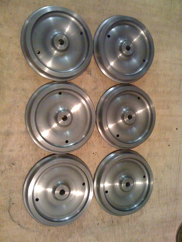
A bit rushed but I got them done at a visit to Number 8 shop in Wrington (my parents house - they have a lathe)

Image
Richard Phillips
Fat Controller
Posts: 178
Joined: Mon Feb 23, 2009 6:14 pm

Post by Richard Phillips » Tue Aug 18, 2009 10:16 am

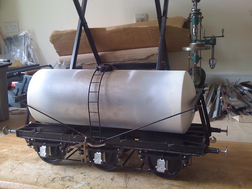
Just got the tanker on a set of dummy axles for it to go into the Bristol ME exhibition, it's not quite exhibition standard but the show is a deadline to keep things moving. I thought the coach wheels looked far to big but once it's on the axles it starts to look like the prototype a bit more.

Image
Keith1500
Fat Controller
Posts: 150
Joined: Tue Jul 04, 2006 8:27 pm
Location: B/Hill, Essex

Post by Keith1500 » Thu Aug 20, 2009 10:16 pm

Turning the profile on the wheels was'nt a problem after all then Richard?

The tank looks good. How did you finish the ends on to the barrel?
Richard Phillips
Fat Controller
Posts: 178
Joined: Mon Feb 23, 2009 6:14 pm

Post by Richard Phillips » Fri Aug 21, 2009 10:52 am

Keith1500 wrote:Turning the profile on the wheels was'nt a problem after all then Richard?

The tank looks good. How did you finish the ends on to the barrel?
Once you know the dimensions then there was no problem. My sequence was this (and I don't advocate it, just the way I did it!)

Mount the wheel in the reverse jaws back facing outwards, clock it, but don't worry about concentricity of the rim at this stage, this is just to face the 1mm off the back.

Check the thickness, I found my HSS tool wore slightly in use so relied on checking the thickness rather than the cross-slide setting

Now here's where I went all bad-practice. I didn't bother making a mandrel until late on, so I actually bolted the wheels to a face-plate, clocked for concentricity to the front face tyre, because the front and back may not be exactly concentric. At this point a centred the wheel and drilled 5/16", I didn't ream at this stage because I don't have an 8mm reamer... I'll probably regret this, but relied on the fact that a 5/16 drill will probably cut slightly oversize to allow a "loctite fit" :roll:

I took the tyre down to close to it's root size leaving a step for the flange.

I made a mandrel in the 3-jaw from a bit of hexagon stock, and threaded 5/16" BSF I think, because that's what I had, (could have stepped it) and used a commercial nut and washer, to my surprise this held firm.

Mounted the wheels in turn and turned the flange down to the final diameter and put in a root radius and close to final angles.

Mounted each wheel in turn and without changing the cross slide and using a stop put the final profile on using a previously ground tool to GL5 profile and tried to avoid chatter.

Used a flat tool with the appropriate angle for the rim. I took some of the chatter marks out with one of those tools you're not really supposed to use in the lathe...

I suppose I did that in about 6 hours, so an hour per wheel.

Lots of cast iron dust, you should probably wear a mask.


Tank Barrel

I ground the weld flush, then drilled some holes in the underside as per instructions.

I put the ends in the lathe and centred them and drilled a hole for the tie-rod and couterbore for the nut. I turned a bit off the tank end at this stage as they're slightly oversize and put the corner radius back on

Bashed the tube round at the seam using a lump hammer and some deft and carefully aimed blows.

Glued the tank ends in, held with the tie-rod, and filled the seam and counterbore with P38 car body filler. The commenced a process of sanding and spraying to check the finish, hence why the tank is white at both end and not in the middle.
Richard Phillips
Fat Controller
Posts: 178
Joined: Mon Feb 23, 2009 6:14 pm

Post by Richard Phillips » Mon Nov 02, 2009 4:28 pm

Right, a bit more progress, mainly on the laborious to make vacuum and steam heat piping.

Being a bit of a cheapskate (actually being broke) I made my own vac pipe ends, a bit overscale and they project too much, but an interesting exercise none the less. The jigs:

Image

The end result:

Image

Tanker on it's saddles with with all the fiddly bits attached:
Image

I'll have to save up for the screw coupling!
Richard Phillips
Fat Controller
Posts: 178
Joined: Mon Feb 23, 2009 6:14 pm

Re: LMS Milk Tank

Post by Richard Phillips » Wed Jan 06, 2010 1:09 pm

Right, Happy New Year and all that. With the new board/website I had to reset my password, so maybe that's why there hasn't been much new here of late. To keep the story going here is a (poor quality!) picture from a while back of progress on the tanker and I've moved on a bit since then.

Image

Hope eveyone's tankers/wagons are coming along...
Keith1500
Fat Controller
Posts: 150
Joined: Tue Jul 04, 2006 8:27 pm
Location: B/Hill, Essex

Re: LMS Milk Tank

Post by Keith1500 » Sun Jan 10, 2010 10:31 pm

Well, well Richard. Good work and it looks very impressive. My wagon build is still stalled due to DIY and rebuilding of the garage/workshop. I did take the chassis out over Christmas to show my brother and very nearly got back in it.

Still, Soon hopefully.

But, be encouraged. Good photos.

Keith
mikeg
Engine Driver
Posts: 26
Joined: Mon Sep 08, 2008 7:46 pm
Location: essex

Re: LMS Milk Tank

Post by mikeg » Mon Jan 11, 2010 7:16 pm

If you can have a look at the 'Model Rail' magazine for july 2008 - it has a very informative article on Milk trains with a few shots of trains/tanks in service. Good info on how these trains were run which is of interest. :)
Post Reply