LMS Milk Tank - 2
Re: LMS Milk Tank - 2
Just starting to look at the brakes.
Which component is the brake trust adjustment bar? Is this the piece on the end of the triangluar cross bars which attaches to the compensating lever. The adjustment being a multitude of holes?
Which component is the brake trust adjustment bar? Is this the piece on the end of the triangluar cross bars which attaches to the compensating lever. The adjustment being a multitude of holes?
-
Richard Phillips
- Fat Controller
- Posts: 178
- Joined: Mon Feb 23, 2009 6:14 pm
Re: LMS Milk Tank - 2
I'm thinking of the bit you have to cut off the truss and turn through 90 degrees, don't know the official name! I have a photo of some full size prototypes somewhere...Keith1500 wrote:Just starting to look at the brakes.
Which component is the brake trust adjustment bar? Is this the piece on the end of the triangluar cross bars which attaches to the compensating lever. The adjustment being a multitude of holes?
There's probably other ways of achieving the same effect. Lengthening or shortening a particular lever, it might be that yours goes together fine, can't say I really understood the whole thing until I bolted it together.
Re: LMS Milk Tank - 2
I thought that might be the bit you were referring to.
I have a good grasp of the brake concept as it is very similar to that on the Toad. (except for one bit pushes)
I'll be cutting off those bits to turn them through 90degrees as per the instructions so I’ll wont solder them until i have checked them for length. Thanks for the tip off.
Hope to do the brakes over this weekend.
Axle ties are all painted and ready for fitting. I added some washers to check the end float on my outer wheels. i found there was nearly 100 thou play on them. the middle one will benefit having play for tight bends.
Re: LMS Milk Tank - 2
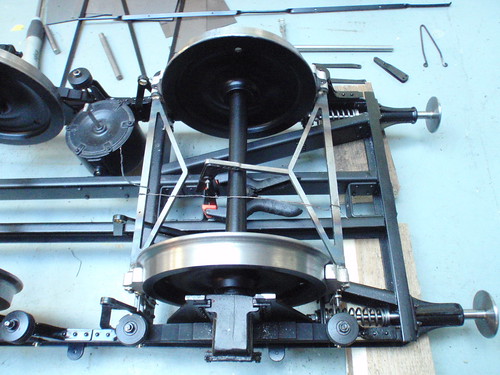
I managed to do the brake shoe assembly for one end today. Here is a photo of the components temporarily held together to see if there were any problems etc. Seemed ok. Though an hole or two would have been good on the adjustment of the brake truss. Its probably worth mentioning here that I machine my wheels to 3.760 inches. ie not the maximum size but half way between max and min - if that makes sense?Richard wrote:
I found I needed to extend the brake truss adjustment bars by about a quarter of an inch I think it was to get it to hook up, I'd be interested to see what you find on this. The prototype had a row of three holes in it (or at least the one at the NRM has).
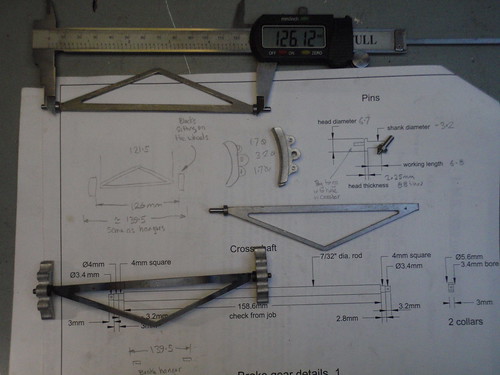
this is the truss components theory
Re: LMS Milk Tank - 2
Well these brakes are certainly a challenging build but it’s coming together nicely. The order of build has been...
Make up the trusses, shoes on to trusses, then hanger on to the shoes and then mount each completed trusses on to the frame. link up the pairs of trusses. Adjust brakes, adjust to first hole setting. Add the long pull rod and then the short push rod to the compensator. Slide in the shaft and check it all works by gentle applying pressure to the compensator mechanism. Its an impressive little mechanism.
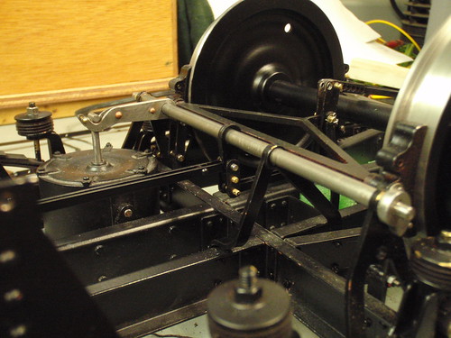
This photo shows the brakes in place, along with the pull and push rods and the compensating levers that come off the shaft.
The shaft is finished and my next job is to tackle each of the lever mechanisms. Do shout if i have made an error anywhere??
Make up the trusses, shoes on to trusses, then hanger on to the shoes and then mount each completed trusses on to the frame. link up the pairs of trusses. Adjust brakes, adjust to first hole setting. Add the long pull rod and then the short push rod to the compensator. Slide in the shaft and check it all works by gentle applying pressure to the compensator mechanism. Its an impressive little mechanism.
This photo shows the brakes in place, along with the pull and push rods and the compensating levers that come off the shaft.

The shaft is finished and my next job is to tackle each of the lever mechanisms. Do shout if i have made an error anywhere??
-
Richard Phillips
- Fat Controller
- Posts: 178
- Joined: Mon Feb 23, 2009 6:14 pm
Re: LMS Milk Tank - 2
I think that was my problem, I set the crank angles on the rod (the vac. crank and the smaller central crank), whereas you haven't done this yet.
By the way, the colour I used for my tank was Halfords Ford Burgundy Red if you want to use the same shade. I have NO idea if this is correct - just close to the Hornby model - which is frustratingly wrong in a number of chassis detail aspects
By the way, the colour I used for my tank was Halfords Ford Burgundy Red if you want to use the same shade. I have NO idea if this is correct - just close to the Hornby model - which is frustratingly wrong in a number of chassis detail aspects
Re: LMS Milk Tank - 2
Yes my instinct was not to set the crank until i had all the other parts in place and then see where it 'wants' to be. What i have decided to do is pin the crank in place. So i have drilled a hole in the underside of the crank and hopefully I will be able to set it and then spot through with a drill on to the shaft.
One thing I noticed; the crank doesn’t need to be out by much, just a degree or two to cause a large variance of the brakes which in turns means taking it up by adjusting. This is probably what you found you need to add some length to the trusses.
The Vacuum brake lever will be set in place with some loctite.
Well, you set the standard for the colour so i am going to follow your lead, otherwise if i use something different the tanks will look add next to each other. At least with a ford paint it'll be available fro a good few years!
when you did the steam and vacuum pipework; how was this run on the underside?
how did you make the brake pin racks?
-
Richard Phillips
- Fat Controller
- Posts: 178
- Joined: Mon Feb 23, 2009 6:14 pm
Re: LMS Milk Tank - 2
I made little clips for the pipes as per a photo of the works drawing I have. There's a cross-over each end so the pipes present on the right side, and you have to kink one of the output brackets (and I thought "why did they do that?" looking at the plan util I came to fit my simplified backets and it landed on a chassis rivet)
I think the steam pipe is a smaller diameter than the vac pipe, I'd need to check again. Can't remember if the clips were a "U" or a "P" shape.
I think the steam pipe is a smaller diameter than the vac pipe, I'd need to check again. Can't remember if the clips were a "U" or a "P" shape.
Re: LMS Milk Tank - 2
Richard,
Any chance of a copy of your photo of the works drawing? Does it show the little hook below the draw hook for stowing the coupling?
I managed to find the ford colour in Halfords but i want to complete the chassis before getting to invovled with doing the tank.
Cheers
Keith
Any chance of a copy of your photo of the works drawing? Does it show the little hook below the draw hook for stowing the coupling?
I managed to find the ford colour in Halfords but i want to complete the chassis before getting to invovled with doing the tank.
Cheers
Keith
Re: LMS Milk Tank - 2
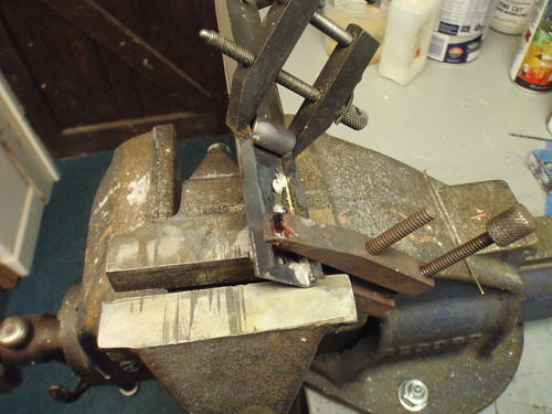
Made a start on the crossbar assemblies.
I turned two spacers 700 thou long to ensure I kept the sides square to the main face.
 [/url][/img]
A lot of soldering. certaainly kept the garage warm !
I turned two spacers 700 thou long to ensure I kept the sides square to the main face.
 [/url][/img]
A lot of soldering. certaainly kept the garage warm !
-
Richard Phillips
- Fat Controller
- Posts: 178
- Joined: Mon Feb 23, 2009 6:14 pm
Re: LMS Milk Tank - 2
Here's some photos of 4457 at the NRM to help you out. Diagonally braced chassis, but similar.
Re: LMS Milk Tank - 2
Richard,
Thanks for posting the above pics and also the other info gratefully recieved. plus your method of making elbows for the vac pipe worked a real treat. Good stuff.
Well, its still upside down !
A few more bits to do before I can turn it up the right way and start work on the tank.
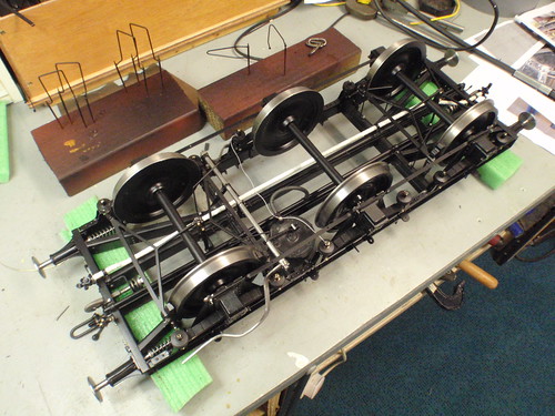
Pipework fitted to the underside. I used wome self amalgamating tape to simulate insulation on the steam pipe. I used home made elbows on the vac pipe as per Richard's idea. I have added a piece to the vacuum brake cylinder to simulate the pipe connection and release valve. Next job is to fit the remaining safety hoops and then start work on the topside.
Question
Are there 10 or 12 safety hoops?
Thanks for posting the above pics and also the other info gratefully recieved. plus your method of making elbows for the vac pipe worked a real treat. Good stuff.
Well, its still upside down !
A few more bits to do before I can turn it up the right way and start work on the tank.

Pipework fitted to the underside. I used wome self amalgamating tape to simulate insulation on the steam pipe. I used home made elbows on the vac pipe as per Richard's idea. I have added a piece to the vacuum brake cylinder to simulate the pipe connection and release valve. Next job is to fit the remaining safety hoops and then start work on the topside.
Question
Are there 10 or 12 safety hoops?
Re: LMS Milk Tank - 2
started work on the tank and its mounts sometime ago. the progress has been time consuming to say the least. Preparation of the tank has taken me ages trying to get a good finish for the gloss to go on to. I forgotten what a skillful job bodywork is. Havent done any since i had a Triumph Herald !
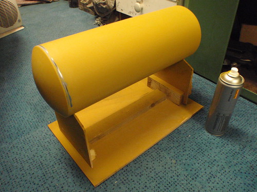
The tank has been painted using Halford filler primer. The next stage is to flat that and apply grey primer.
Then leave for a day to settle and then flatten and give it a first coat of finish to see what i have missed!
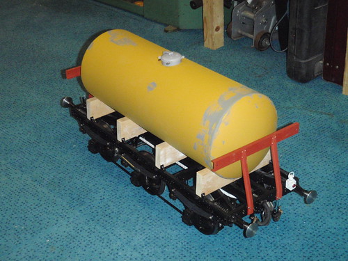
Hope there still someone out there - its awfully quiet !

The tank has been painted using Halford filler primer. The next stage is to flat that and apply grey primer.
Then leave for a day to settle and then flatten and give it a first coat of finish to see what i have missed!

Hope there still someone out there - its awfully quiet !
Re: LMS Milk Tank - 2
There are still people looking and certainly in my case interested in following your progress. It is all looking to be coming along very nicely.
Re: LMS Milk Tank - 2
I thought it best if I made up the straps and the ladder next before I paint the tank and risk scratching it.
This afternoons job was the four straps. Threaded 8BA on 2.5mm rod for the fastenings. I worked the straps around a tin of P38 filler using a small soft hammer. Centred them across the tank and cut them 14mm above the bracket.
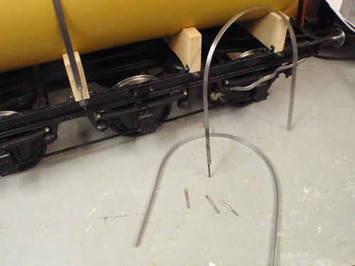
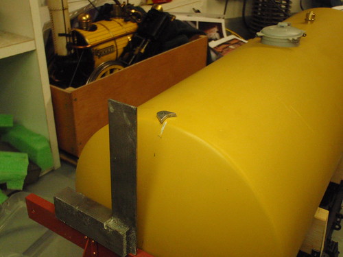
I have also added the fittings to the tank, namely the outlet pipes and the lifting lugs. Having fitted the outlet pipes and got these sitting directly above the coupling hook, ie the bottom of th ebarrel is now centred, I aligned the lifting lug at the top by diving the cross bar and projecting the line upwards with a square. The mark in the paintwork is allow the araldite to key on to the resin end not just the paint.
This afternoons job was the four straps. Threaded 8BA on 2.5mm rod for the fastenings. I worked the straps around a tin of P38 filler using a small soft hammer. Centred them across the tank and cut them 14mm above the bracket.

I have also added the fittings to the tank, namely the outlet pipes and the lifting lugs. Having fitted the outlet pipes and got these sitting directly above the coupling hook, ie the bottom of th ebarrel is now centred, I aligned the lifting lug at the top by diving the cross bar and projecting the line upwards with a square. The mark in the paintwork is allow the araldite to key on to the resin end not just the paint.

Re: LMS Milk Tank - 2
As it wont be long before the tank is ready to be mounted I though I had better mount the splasher plates.
As the end ones sit under the tank supports, the tank supports needed to have a rebate cut to acomodate the splashers. then with a little glue they can be held in place.
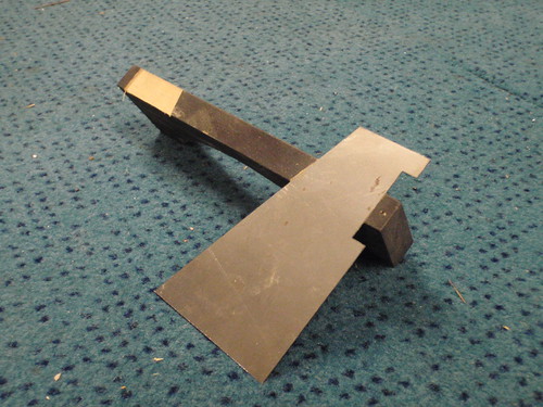
The middle ones were a little more tricky. They have their ends turned up and in full size these were bolted/screwed to the supports. So i used this principle and attached them using 4No 1/32nd rivets. these have been pushed into the corresponding holes with a little super glue on them.
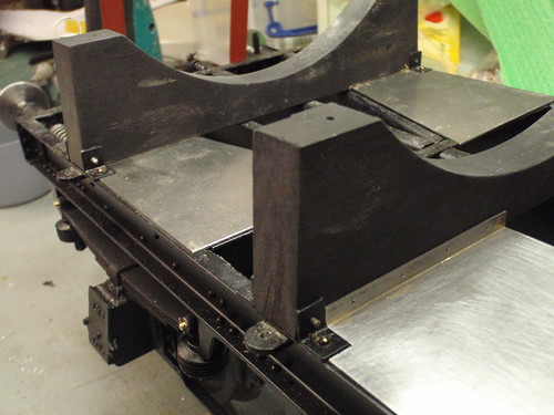
Apparently there was a leather strip between the tank and its wooden supports. For this I glued in place some self amalgamating tape. This will also protect the paint work as the tank is mounted and removed a few more times during the application of transfers etc. Well thats the theory!
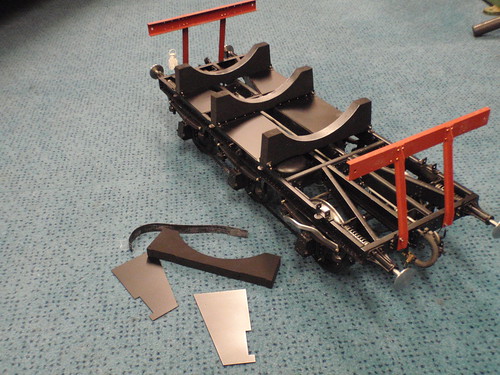
still need to finalise the brake hand racks befor ei commit to mounting the tank. Getting there....
As the end ones sit under the tank supports, the tank supports needed to have a rebate cut to acomodate the splashers. then with a little glue they can be held in place.

The middle ones were a little more tricky. They have their ends turned up and in full size these were bolted/screwed to the supports. So i used this principle and attached them using 4No 1/32nd rivets. these have been pushed into the corresponding holes with a little super glue on them.

Apparently there was a leather strip between the tank and its wooden supports. For this I glued in place some self amalgamating tape. This will also protect the paint work as the tank is mounted and removed a few more times during the application of transfers etc. Well thats the theory!

still need to finalise the brake hand racks befor ei commit to mounting the tank. Getting there....
-
Dave Harris
- Engine Driver
- Posts: 33
- Joined: Mon Sep 26, 2005 11:27 pm
- Location: Frome
Re: LMS Milk Tank - 2
Keith,
Many thanks for putting up pictures of your work on the milk tank for all of us to see and enthuse over, it cetainly looks very nice.
One question:....What size rivets are you using on the chassis? I ask because I was told that maximum size rivets we should be using on steel wagon chassis should be 5/64 or 1/16, and yours seem to be a bit bigger than that, and other wagon chassis i have seen recently also seeem to be using bigger rivets?
Re: LMS Milk Tank - 2
Dave thank you for your encouragment and likewise from Richard too.
Re: Rivets. The rivets used on this wagon are 1/16th. There is also alot of 10BA and a few 12BA screws all of which I think is pretty much close to scale.
I know on my GW Toad I used a rivet with a different head profile. It was a larger diameter head with less of a bump if you see what I mean, where as these rivets are finished with a standard bump. Sorry that not technical but how else do you describe a rivet !
If I stand back and compare the model with a photograph of, say one of the ones you kindly pictured for me, I think it looks spot-on.
why what are you building?
Keith
-
Dave Harris
- Engine Driver
- Posts: 33
- Joined: Mon Sep 26, 2005 11:27 pm
- Location: Frome
Re: LMS Milk Tank - 2
Keith,
Thanks for the rivet details, and yes...how else does one describe a rivet.
It was the larger diameter head that foxed me, having seen similar on a couple of chassis at exhibitions last year.
I have a 'Toad' brakevan chassis kit which im trying to sort out, its going very slowly as I suffered a stroke earlier in the year which has given me some mobility/dexterity and short term memory problems, which are improving but combined with a cold garage workshop have slowed things right down...but hey, I will get there eventually. Keep up the good work , along with Richard, it gives us all encouragement
All the best for Christmas and the new year
Dave
Re: LMS Milk Tank - 2
Dave,
I have posted a photo of my Toad in a new thread for you. Hope it may help.
Cheers
KB
I have posted a photo of my Toad in a new thread for you. Hope it may help.
Cheers
KB
